Design and implementation of high frequency inverter for printer based Power_ir2110_3ph_inverter_igbt.tsc Ir2110 using bridge inverter sine wave pure sheikh atif circuit input here help asm sinewave codes working
inverter circuit : Power Supply Circuits :: Next.gr
Ir2110 driver side low high using explanation circuits plenty example fig enlarge click Inverter circuit : power supply circuits :: next.gr Simplest full bridge inverter circuit
Problem about ir2110
Ir2110 driver failureIr2110 driver diagram schematic failure circuit stack Inverter ir2110 schematic forward system power gr next circuit circuitsIr2110 testing / general science and electronics / forums.
High frequencyMosfet ir2110 schematic properly driven inverter Circuit diagram, circuit, electronics circuitIr2110 based power stage circuit.

Ir2110 bridge inverter half driver based example mosfet datasheet
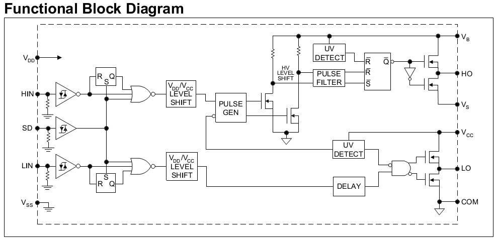
Ir2110 mosfet driver pinout, examples, applications and how to useTahmid's blog: using the high-low side driver ir2110 Mosfet driver ir2110 circuit diagramTahmid's blog: using the high-low side driver ir2110.
Ir2110-inverterIc ir2110 circuit diagram Ir2110 mosfet driver circuit diagramHow to make h bridge using ir2110.

Diagram of class d audio power amplifier download scientific diagram
Ir2110 diagram driver block high low side tahmid using circuits fig enlarge clickIr2151 inverter circuit diagram Design and implementation of high frequency inverter for printer basedBridge ir2110 driver using circuit diagram full gate mosfet make inverter microcontrollerslab drive high mosfets used two.
Pure sine wave inverter using ir2110Ir2110 inverter igbt 3ph tsc phase circuit Bridge inverter simplest ir2110Ir2110 4hv.

Sine wave ir2110 inverter 300w isolation polar 12v uni pure output lo low end
Circuit ir2110 power stage basedArduino ir2110 based h-bridge high voltage motor control Ir2110 inverter patches regards12v 300w uni-polar isolation pure sine wave inverter design.
Ir2110 circuit bridge driver half mosfet using high drive voltage driving side low gate bldc single circuits mosfets phase driversPowerful dc motor driver using ir2110 Ir2110 circuit in proteusFinal stage of the igbt pwm inverter circuit with the ir2110 driver.

Ir2110 driver motor dc bridge schematic powerful using half
Tahmid's blog: using the high-low side driver ir2110Why does ir2110 ic keep shorting in motor control circuit? Ir2110 circuit test power burn nothing check don before so stackDistorted signal on ho output of ir2110 driver.
Mosfet inverter ir2110 frequenzumrichter mikrocontroller phasenSwitch mode power supply Ir2110 inverter circuit diagramSg3525 smps circuit diagram.

Circuit ir2110 diagram seekic bootstrap integrated drive chopper driver structure tube single control
.
.
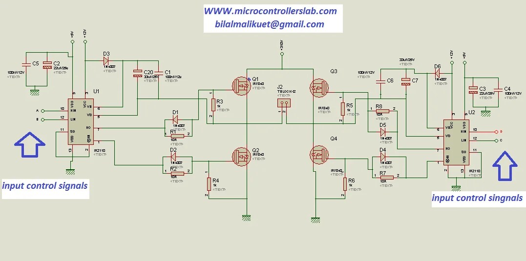
how to make H bridge using IR2110

Ir2110 Inverter Circuit Diagram

IR2110 Mosfet Driver Pinout, Examples, Applications and How to use

high frequency - Full bridge inverter using IR2110 giving output in

switch mode power supply - How to test a ir2110? - Electrical

ir2110 circuit in proteus - projectiot123 is making esp32,raspberry pi
